A planned solar rail can land beside a drain and narrow the service path. We start by mapping the roof zones, seams, penetrations, and access routes. Then we check the existing assembly and mark which questions belong to the structural engineer, roofer, and solar contractor.
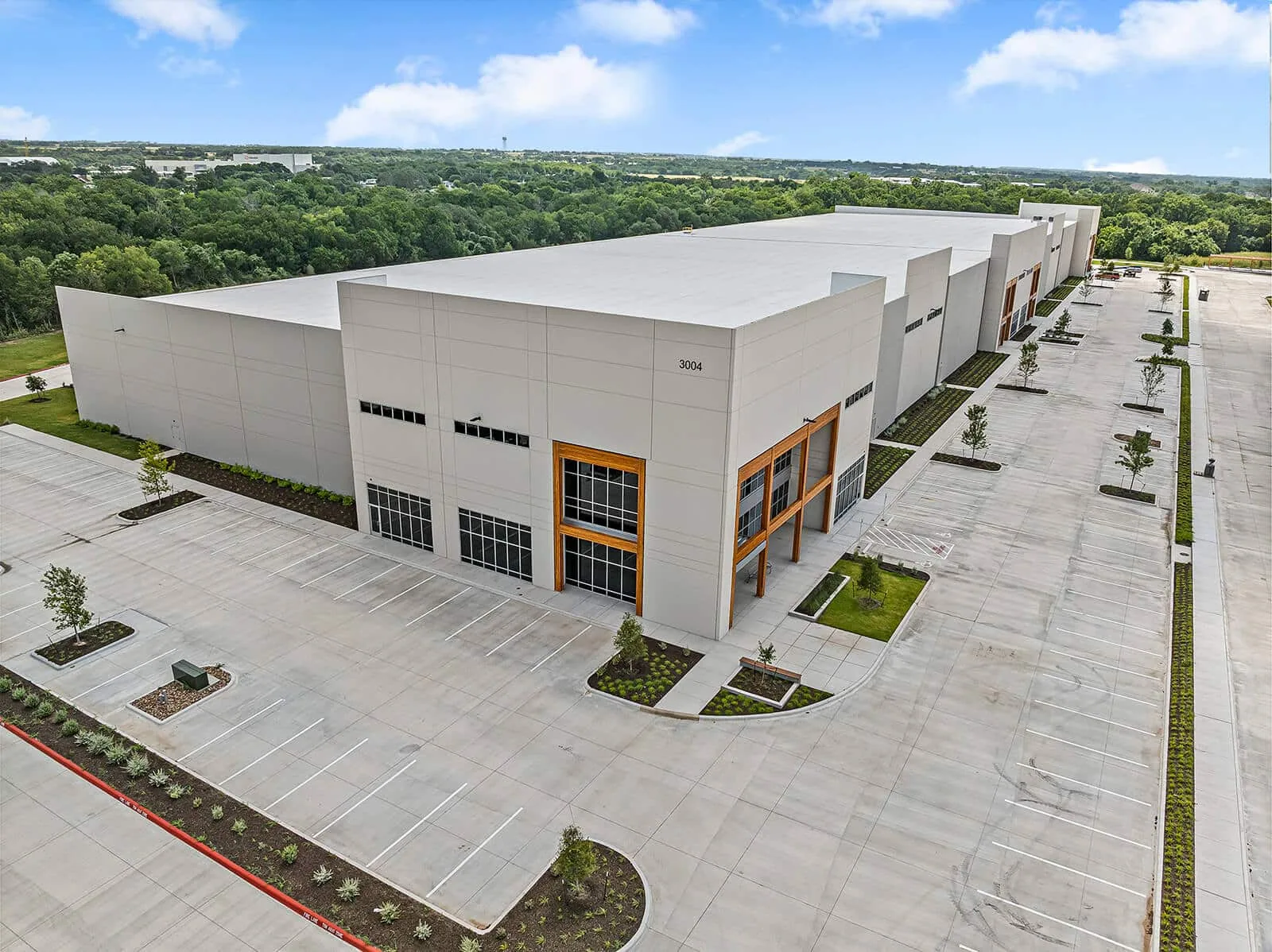
Georgetown's industrial pipeline includes NorthPark35 and Georgetown Logistics Park, with city utility work planned for additional business and speculative industrial buildings. We inspect each roof and identify the condition, access, and attachment details the array design still needs.
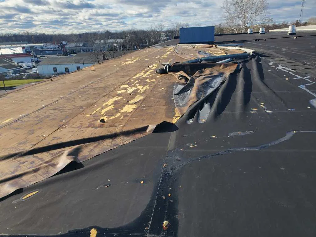
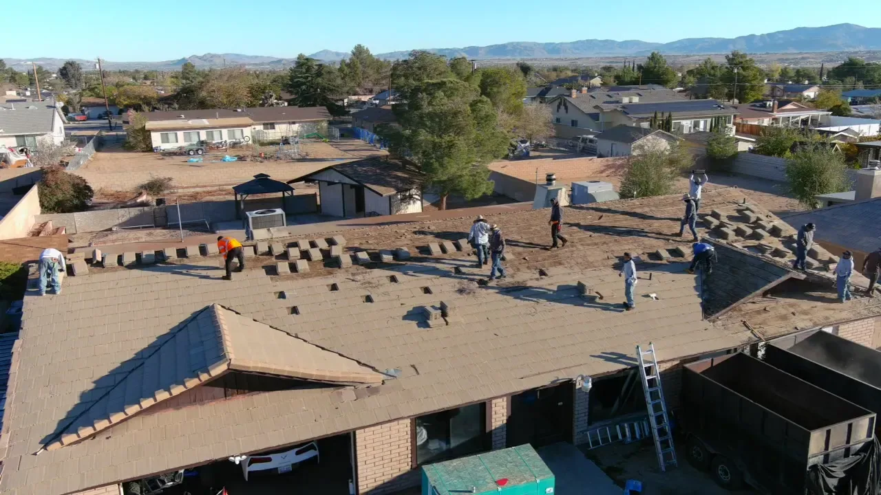
We identify the membrane or panel system, installation history, repair areas, attachment, and visible moisture concerns. A roof with widespread wear may need repair or renewal before new equipment is installed. A local patch beside a rail does not fix a larger pattern. The roof map records each section and the condition that affects the solar boundary.
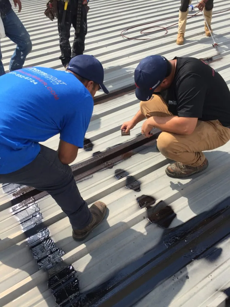
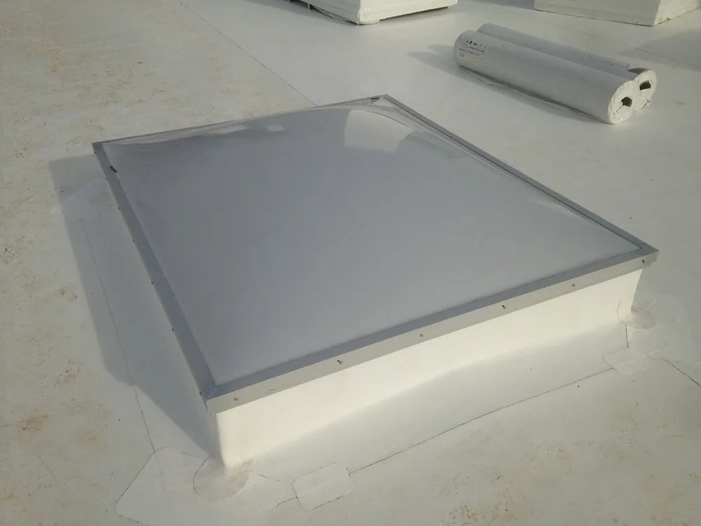
We note drains, scuppers, curbs, skylights, expansion joints, and perimeter details. The array layout must leave access to those features for inspection and service. If a roof opening is needed to confirm layers, we mark a hold point before structural design relies on the assumed assembly. A condition inspection can establish that starting record. A recover review can determine whether the existing roof remains suitable for another layer.
Georgetown's summer heat and regional hail exposure affect roof condition and work timing. We check sealants and exposed seams before layout review. The weather record does not determine remaining service life. That judgment follows the roof condition, documentation, and any testing the project team authorizes. We compare repair history with visible wear and identify whether known wet areas or recurring leaks overlap the proposed array. If they do, resolve the repair before the solar layout closes that access. The project file should state which roof zones were inspected and which require follow-up.
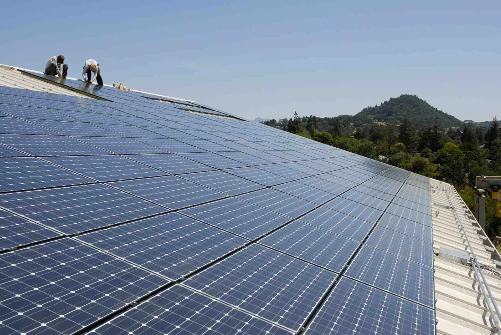
Solar equipment adds dead load and can create wind forces at rails, supports, and attachment points. The structural engineer reviews the building and proposed array. We provide roof assembly information where available and identify membrane, deck, and attachment conditions that may affect the design. We do not approve structural capacity from a visual roof walk.
Attachment choices must preserve the roof system. Penetrations need compatible flashing and a documented tie-in. Ballasted systems still affect loading and can block drains or service routes. We coordinate locations with the array designer and identify details that require engineering approval before the roofer opens the membrane. The equipment support scope can align similar roof penetrations and bases. A flashing review can account for nearby skylights or curb details.
Keep rail locations, conduit runs, inverter connections, and maintenance paths on the coordinated roof plan. If the array layout changes after roof work begins, the team checks the membrane detail again. We set a hold point before drilling or covering the completed roof tie-in. The installer checks each penetration before it is loaded or concealed. The roof crew records the membrane preparation and completed flashing while the detail remains visible. If the rail position shifts, the team confirms the new location and patches the abandoned point with a compatible method. The project record also names who can authorize panel removal for future roof service and how the exposed section will be protected.
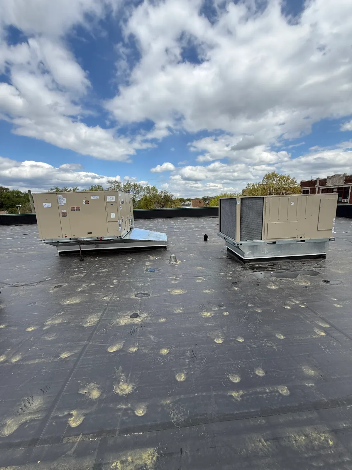
Panels can reduce access to seams, drains, and equipment. The layout should preserve routes for roofing inspections and future repairs. We identify clearance around scuppers, skylights, curbs, and roof edges. We also mark locations where a module would cover a known repair or a roof detail that needs periodic review.
Berry Creek Business Park is a multi-building industrial setting near I-35 and SH 130. For a portfolio project there, each roof needs its own map and array boundary. A layout from one building should not be copied to another without confirming deck, membrane, curb locations, and access rules. The Berry Creek service area gives broad local context; the individual roof walk sets the work plan.
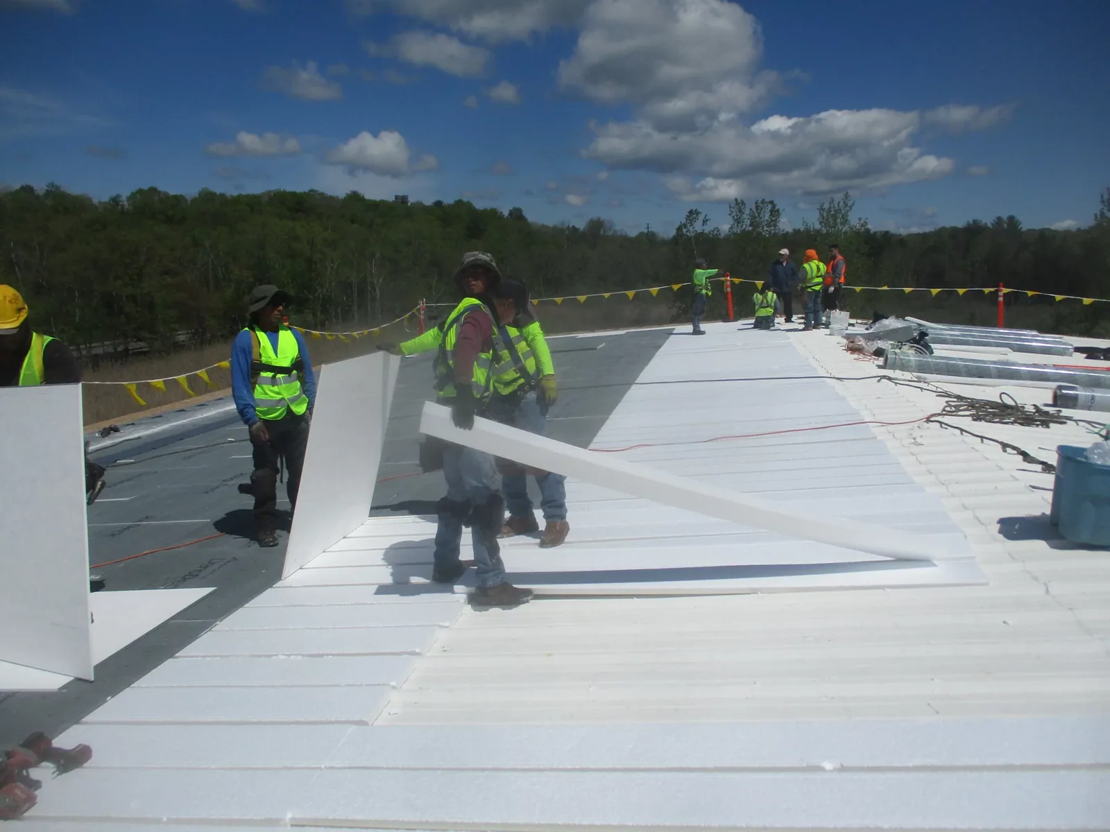
We coordinate panel delivery, staging, crane access, and protection for finished membrane. The solar crew should know where it can walk and where temporary protection is required. After installation, the roof map records inaccessible zones so future maintenance does not assume those details were inspected. The owner should also retain the array layout and mark removable panels or access points needed for roof service. A planned route reduces the risk of foot traffic crossing fragile transitions or dragging equipment over seams.
Hail can affect panels, flashings, rooftop equipment, and roof surfaces. Wind can shift loose components or challenge attachments. The National Weather Service documented a 2022 tornado track across Williamson County, after it began near Round Rock. Those records support a post-event review. They do not prove damage at a specific array or building.
We photograph visible conditions and record the date, roof section, and access limit. If the array blocks a close view, the report says so. The solar contractor and property contact coordinate access before modules are moved. A hail assessment can distinguish visible impact from ordinary wear. A storm repair scope can address any roof defect confirmed during the walk.
Installation timing also depends on dry-in and weather windows. We identify how a roof opening will be protected if rain or wind interrupts work. The general contractor sets a hold point before panels cover a new seam or flashing detail. That leaves a clear handoff between roofing and solar crews.
A solar-ready scope identifies what the roofer inspects, what the structural engineer reviews, and what the solar contractor installs. It lists roof repairs, attachment details, service clearances, and areas that remain uncertain. We document test openings and close them with compatible materials. Added work waits at the agreed hold point.
Cost and timing depend on roof repairs, access, attachment type, array layout, staging, and how much existing material needs correction. If replacement is needed, the roof renewal scope should coordinate solar sequencing before equipment arrives. A photo condition record can preserve the pre-installation baseline and later tie-in details.
Send the roof plan, array layout, access window, and general-contractor contact. We can map the roof boundary and identify which details must be resolved before the solar crew mobilizes. For an active leak outside normal hours, emergency response remains available, including holidays.
It documents roof condition, assembly details, access routes, and repair needs for the project team. Structural capacity and array design still require review by the qualified engineer and solar designer.
The roof condition and project life plan inform that decision. We inspect the assembly, map repairs, and identify whether the roof can support the planned work without making an unsupported life estimate.
Attachment details must fit the roof system and approved design. We coordinate the penetration, flashing, and tie-in with the array contractor and structural engineer before installation.
Modules can restrict access to seams, drains, and equipment. We mark service paths and record any areas that cannot be inspected after installation.
Send the current roof plan, proposed array layout, equipment routes, access rules, and project schedule. We can set inspection limits and roof-trade hold points.